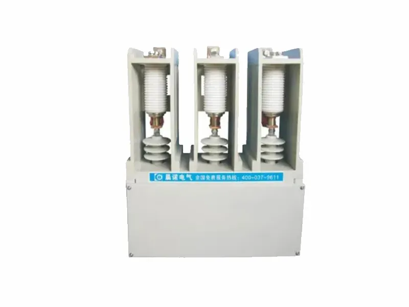
TBBW-10kv(12kv) Outdoor Reactive Power Compensation Device
This series of high-voltage reactive power compensation devices are mainly used for capacitive reactive power compensation and inductive reactive power compensation in the power system with power frequency of 6kV-10kV, so as to adjust and balance the grid voltage, improve the power factor, reduce line loss, improve power quality, and give full play to the production efficiency of power generation, power supply equipment and electrical equipment.
This device adopts a frame structure, constructed from standard components (such as beams, crossbeams, and horizontal bars) connected by bolts.
Equipped with mesh gates on all sides, making it suitable for stable loads in adverse environmental conditions.
Low cost and easy transportation.
Reactor Application
The device is generally equipped with dry-type hollow reactors installed at the neutral point or power supply side to limit inrush currents, suppress high-order harmonics, and improve voltage waveforms.
Inrush Current Limiting: Reactance rate of 0.5%-1%
Suppression of Harmonics above 5th Order: Reactance rate of 4.5%-7%
Suppression of Harmonics above 3rd Order: Reactance rate of 12-14%
Technical Parameters
Power Factor: Can reach up to 0.95 after compensation.
Capacitor Characteristics: Utilizes full-film dielectric capacitors with high reliability, long life, low losses, and good sealing performance.
Voltage Endurance: Can operate under steady-state overvoltage of 1.1 times the rated voltage for a long time.
Overcurrent Endurance: Can continuously operate with a root mean square value not exceeding 1.3 times the rated current.
Control Method Supports local control, centralized control, or automatic control based on user requirements.
Main Technical Performance Indicators
1. Capacitance Deviation: The actual capacitance deviation from the rated capacitance is within 0 to +5%, with the maximum to minimum capacitance ratio between any two terminals not exceeding 1.02.
2. Inductance Deviation: Under rated current, the allowable deviation of reactance is 0 to +5%, with the reactance of each phase not exceeding ±2% of the three-phase average.
3. Insulation Level:
|
Rated voltage of the device |
1min power frequency withstand voltage of primary circuit (rms) |
Primary circuit impulse withstand voltage [(1.2-5)/50μs peak] | Secondary circuit 1min power frequency withstand voltage (RMS value) |
| 6 | 32 | 60 | 2 |
| 10 | 42 | 75 | 2 |
| 35 | 95 | 200 | 2 |
4. Overload capacity
(1)Steady-state overvoltage
|
Power frequency overvoltage U |
Maximum duration | Illustrate |
| 1.1 | long-term | The maximum value of long-term overvoltage does not exceed 1.10UN |
| 1.15 | 30min every 24h | Adjustment and fluctuation of system voltage |
| 1.2 | 5min | The voltage rises at light loads |
| 1.3 | 1min | The voltage rises at light loads |

Double-Pole Low Voltage Vacuum Contactor (CNE2)
This series of vacuum contactors reaches a high level of ...
See More
Single-Phase Low Voltage Vacuum Contactor (CNE )
This series of vacuum contactors reaches a high level of ...
See More
JCZ8C-6kv(7.2kv)/10kv(12kv) Series Medium Voltage Vacuum Contactor
This series of medium-voltage vacuum contactors uses ...
See More
JCZ5-6kv(7.2kv)/10kv(12kv) High Voltage Vacuum Contactor
The series of medium voltage vacuum contactors feature an ...
See More
AC/DC Combiner Boxes for Solar Power Systems
The PV Combiner Box includes both AC and DC Combiner Boxes, ...
See More
Vacuum Circuit Breaker with Permanent Magnetic Actuator (ZN3A-12 )
This series of high-voltage permanent magnet vacuum ...
See More
Low Voltage Panel Box
The terminal box is made from high-quality cold-rolled ...
See More
Vacuum Contactor (JCZ8C-24kV )
This series of medium-voltage vacuum contactors is suitable ...
See MoreProduct Search
Here you can choose products online and find the products you want more quickly and accurately.
Customized Consultation
If you want to customize a product, please contact us, and our team is more than happy to assist you.
Product Procurement
If you want to purchase a product, please contact us and we will provide you with product information and a quotation.
Tel:+86 15538537280
Email:lycnelectric@163.com
Add:No. 9 Duyu Street, Luolong District, Luoyang City, Henan Province